Following on from the Cat Badge that I previously designed, I wanted to build one based around an Elephant, since I wanted it to be related to PostgreSQL.
Design
I want to stick to the same design aesthetic, with a simple 3 colour geometric approach.
My initial idea was to try and use the PostgreSQL logo directly as the basis for the design, but I couldn't come up with a nice way to incorporate the LEDs into it. So I decided to go a bit more abstract.
I remember Citus having some striking geometric elephant designs from previous PostgreSQL conferences. Yet I couldn't see how to nicely incorporate the LEDs into such a design, with out it going more towards string art.
I realised that since the Cat was straight-lined and angular. I wanted this design to more feature flowing curves, that is still in keeping with the Art Deco original inspiration.
I'm my no means an artist, and frankly can draw for shit. I did sketch out a few design ideas on paper: some angular, some curvy. Before starting to draw anything in Inkscape .


Iterating The Circuit
I used the orginal Cat schematic as the starting point, wanting to stay as consistent as possible. The design makes use of an ATtiny1616 as the main microprocessor and wires the LEDs into a matrix to use the least number of IO pins possible while still enabling individual control of each LED. The IO pin mappings where tweaked to make PCB layout easier, since these pin mappings can easily be handled by the firmware. This time I used more columns (which are PWM controlled) to keep all LEDs of a column the same colour.
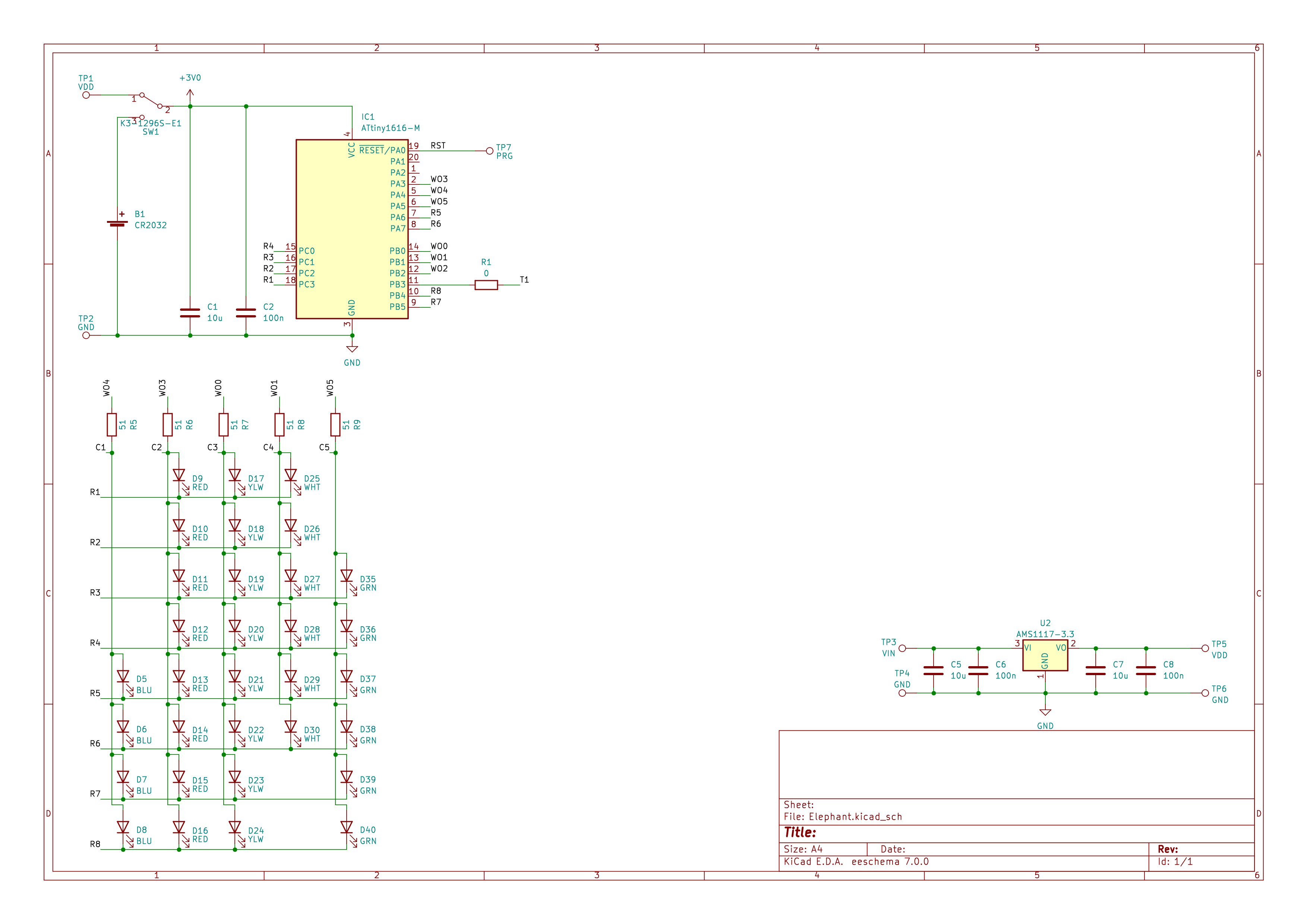
The voltage regular in the schematic is not used by the main badge body, but designed for a display stand which can be powered from a USB cable.
With the original Cat design I incorporated a number of sensors: temperature, light and sound. To a large extent these were thrown in as an experiment, without any real intended purpose. It turned out making any use of the microphone was pretty difficult, I never used the temperature sensor. However did make the design use the light sensor to alter the brightness.
One significant change I made was to add a power switch (albeit a bit late in the design/development process), user testing of my cat badge really showed that 'take the battery out' was not really a good approach to power control.
Initially I decided to just keep the light sensor and make keep the dynamic brightness controls, however I ended up dropping this due to space and routing issues.
Layout
I used the same approach as with the Cat design, importing the board outline from the SVG files I designed in Inkscape, I designed the vectors in Inkscape with the final dimensions, rather than having to scale the design on import into KiCAD. I split out the various solder mask relief vectors in Inkscape and imported these separately into KiCAD.
The design looks deceptively simple to route! Yet there are a few little complications which all add up to it being a little irritating, taking about 8 hours to manually route the final design.
While the power switch is a tiny 9mm by 4mm microminiature slide switch, it was surprisingly hard to place. It didn't help that my revelation to add a power switch came after I'd almost routed the whole first design. While the design has a fair amount of space there are lots of limiting constraints.
At the end of the day the aesthetics of the piece are the highest priority, so there are certain areas that traces cannot pass. Combined with being a 2 layer design to keep costs down this meant there are certain areas of the board with lots of traces hoping from side to side. This made routing the main power traces a little more irritating that normal.
The bigger complication is all the LEDs are laid out in circular patterns. Thankfully KiCAD has good tools to layout components in these days, once knowing the centre and radius.
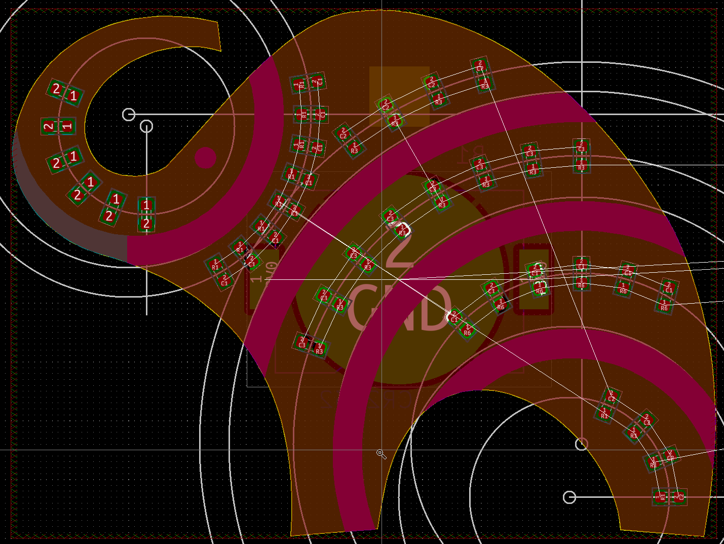
I made good use of creating circular arrays, I found it's best to start these from vertical or horizontal parts. You need to manually compute the spacing angle which looks best and then apply this rotation to each patterned part. Laying out the parts was probably the easiest part. Routing required often switching modes in the interactive router, since walk around mode can only handle 90 and 45 degrees.
32 LEDs
Some of my original layout iterations had more than 32 LEDs on the design. The LEDs are all wired in a matrix, where the microprocessor has to drive one pin high and one pin low to flow current though an LED and light it. I also make use of the PWM channels for brightness control, this limits the circuit to at most 6 columns. The number of rows is mostly limited by the number of IO pins which remain: at least 8.
My second iteration of the firmware of the Cat design moved the LED patterns to OP codes which are interpreted by a very simple byte code interpreter. Given this is all running on a microprocessor with (a whopping) 2KiB of RAM and 16KiB ROM, it might seem silly and excessive. Yet it actually enables super efficient use of flash storage.
This OP code interpreter uses 3 bits for the operation and 5 bits for data, so 32 is the limit of the number of LEDs. To be honest I only realised once the PCBs had arrived that I had accidentally designed to this constraint.
For this design I also added OP codes to directly control the matrix rows and columns, allowing for more complex patterns to be defined which can light more than one LED at a time.
Assembled PCB Panels
I designed a custom panel in KiCAD in order to meet the PCB assembly minimum size requirements, and got the top side assembled by the PCB manufacturer. Manually placing so many 0603 LEDs is not much fun.
I had to hand solder the back mounted battery clips and power switch, thankfully this is pretty easy. I had selected a power switch from LCSC (in case I wanted both sides assembled). Having ordered the boards I needed to find an alternative part I could get from Mouser in time, thankfully after a little bit of hunting I found a part which matched the footprint.

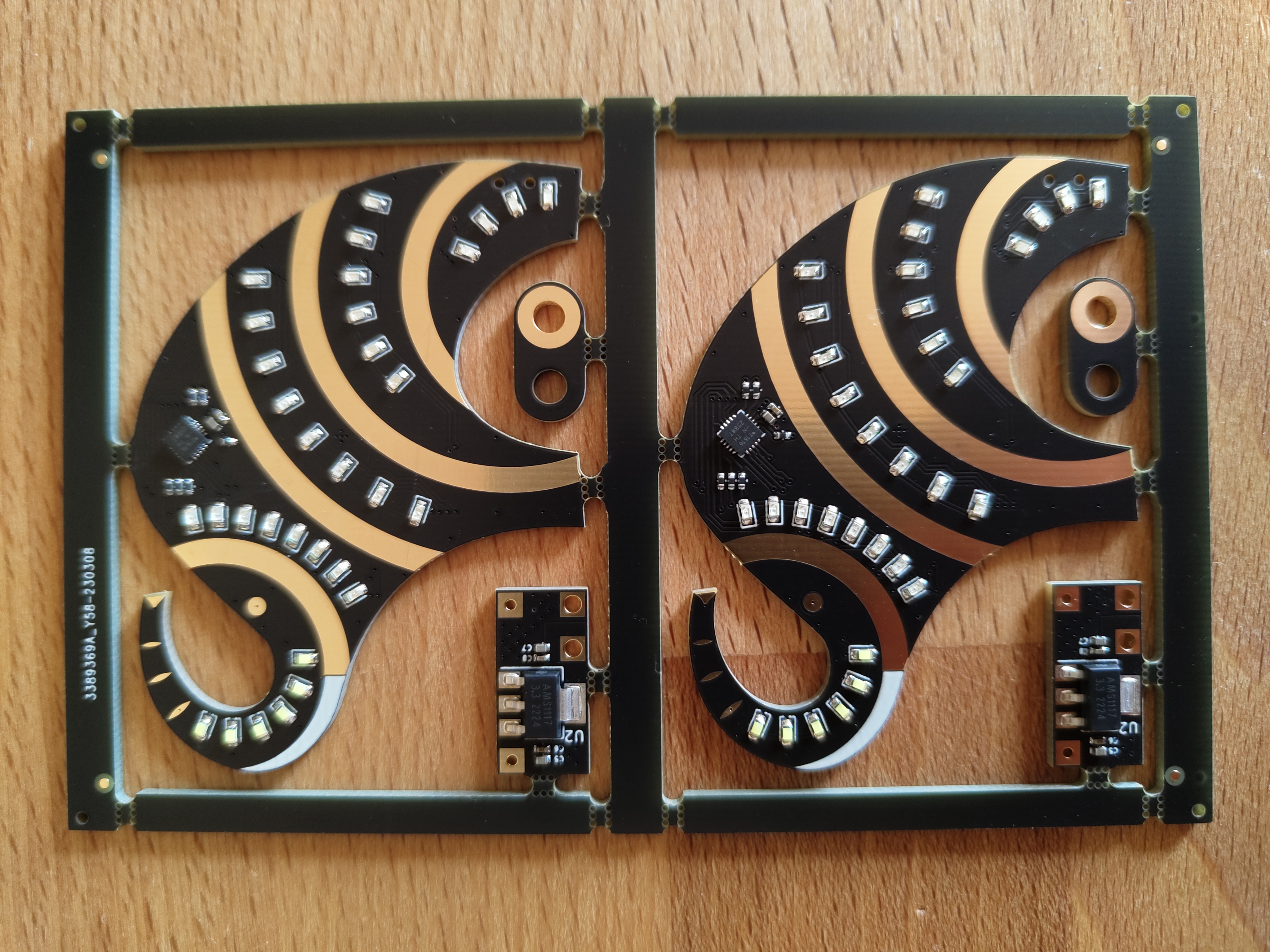
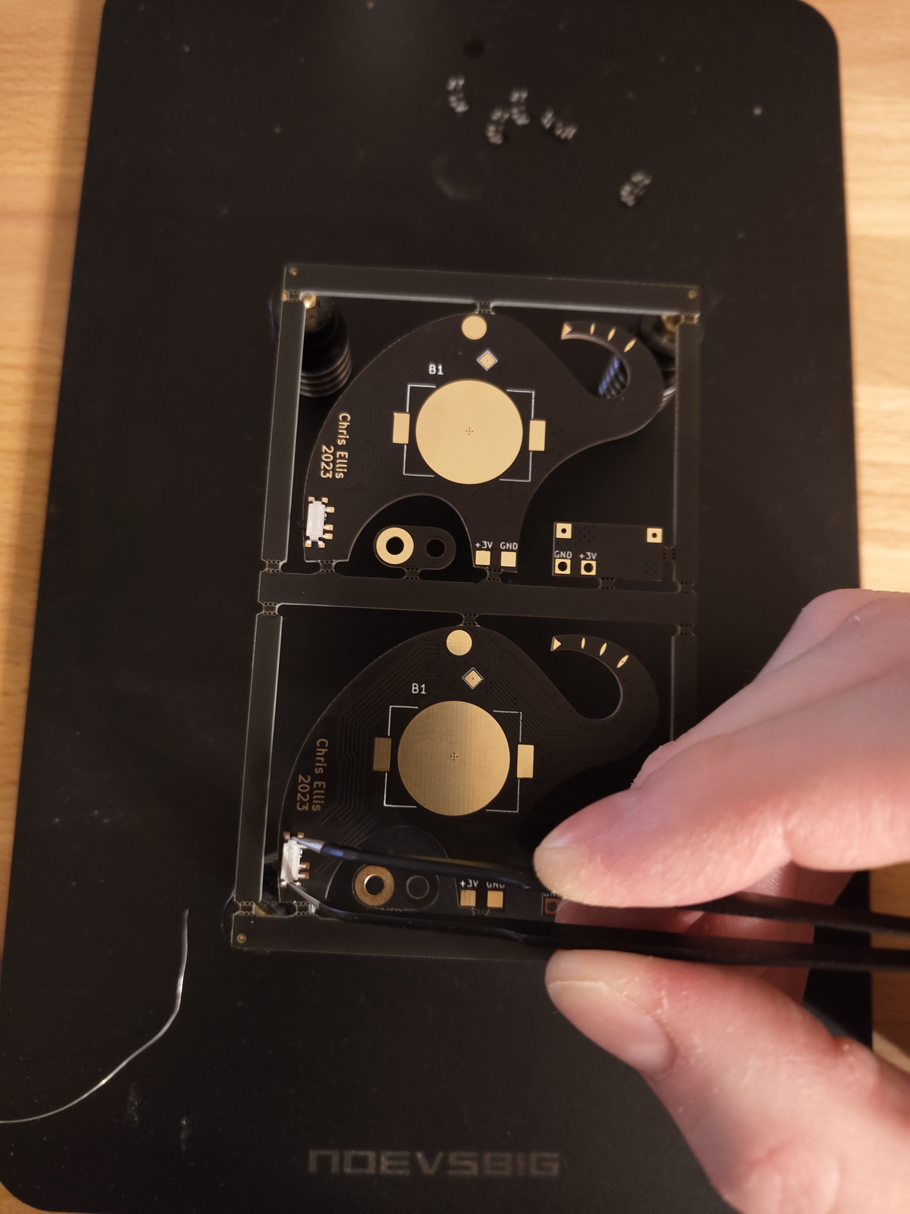
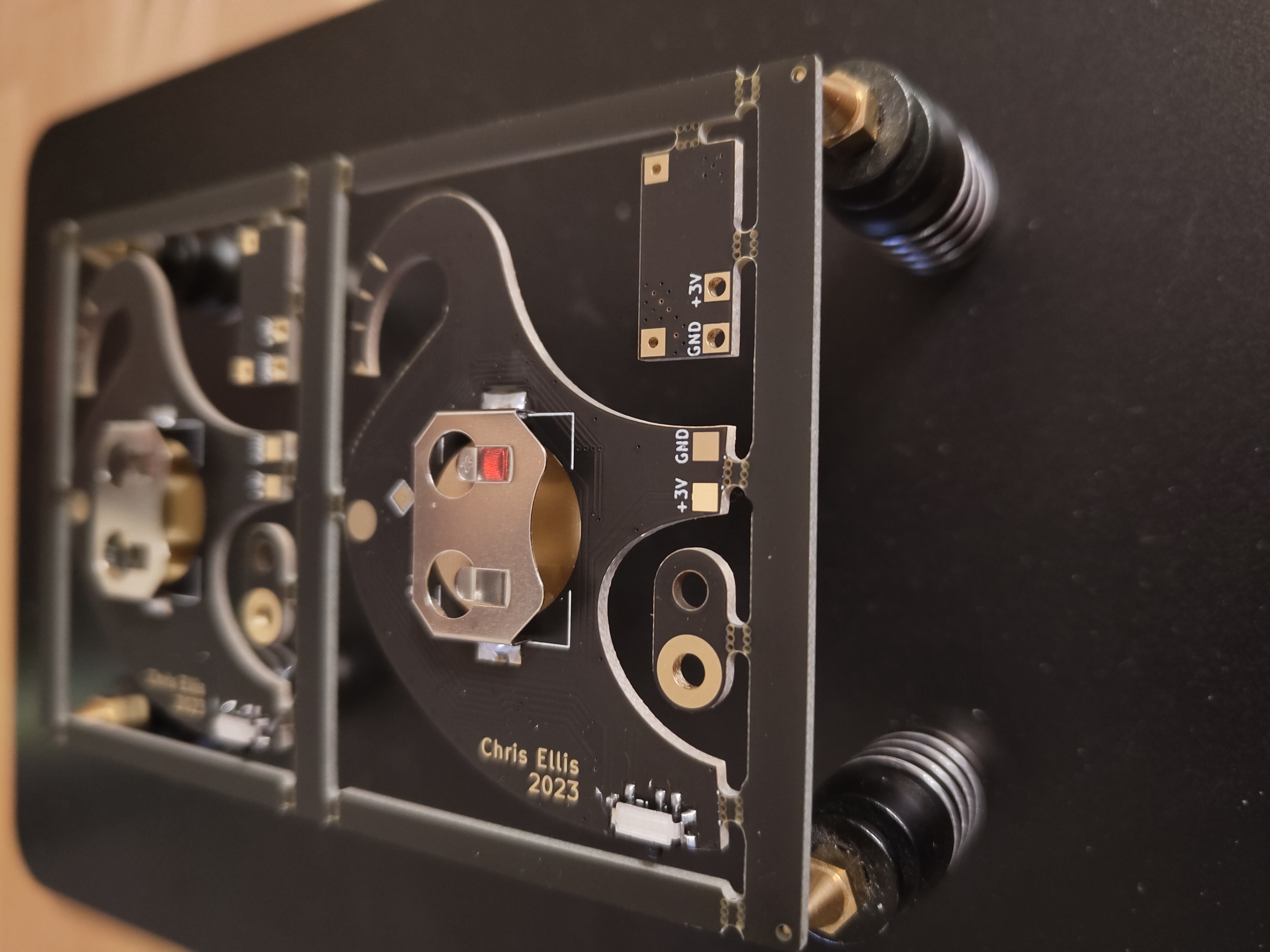
On the panel I also included a little voltage regulator board, to enable an optional desk stand which could be USB powered, there are two pogo pins (spring loaded plungers) which contact two pads on the back of the PCB to provide power.
Another element in the panel is an optional key ring hanger, which can be soldered to the back of the board rather than a badge pin.
Programming
The badge uses an ATtiny1616 microprocessor to control the LEDs which are wired in a matrix to use the least number of IO pins to control the LEDs. The firmware has a very simple OP code interpreter which allows the flash patterns to be stored in constant byte arrays (these get stored purely in flash ROM).
The firmware is unified across the different badge designs, with the LED patterns defined in header files which can be selected at build time. This unified firmware is Open Source if you want to try defining your own patterns.
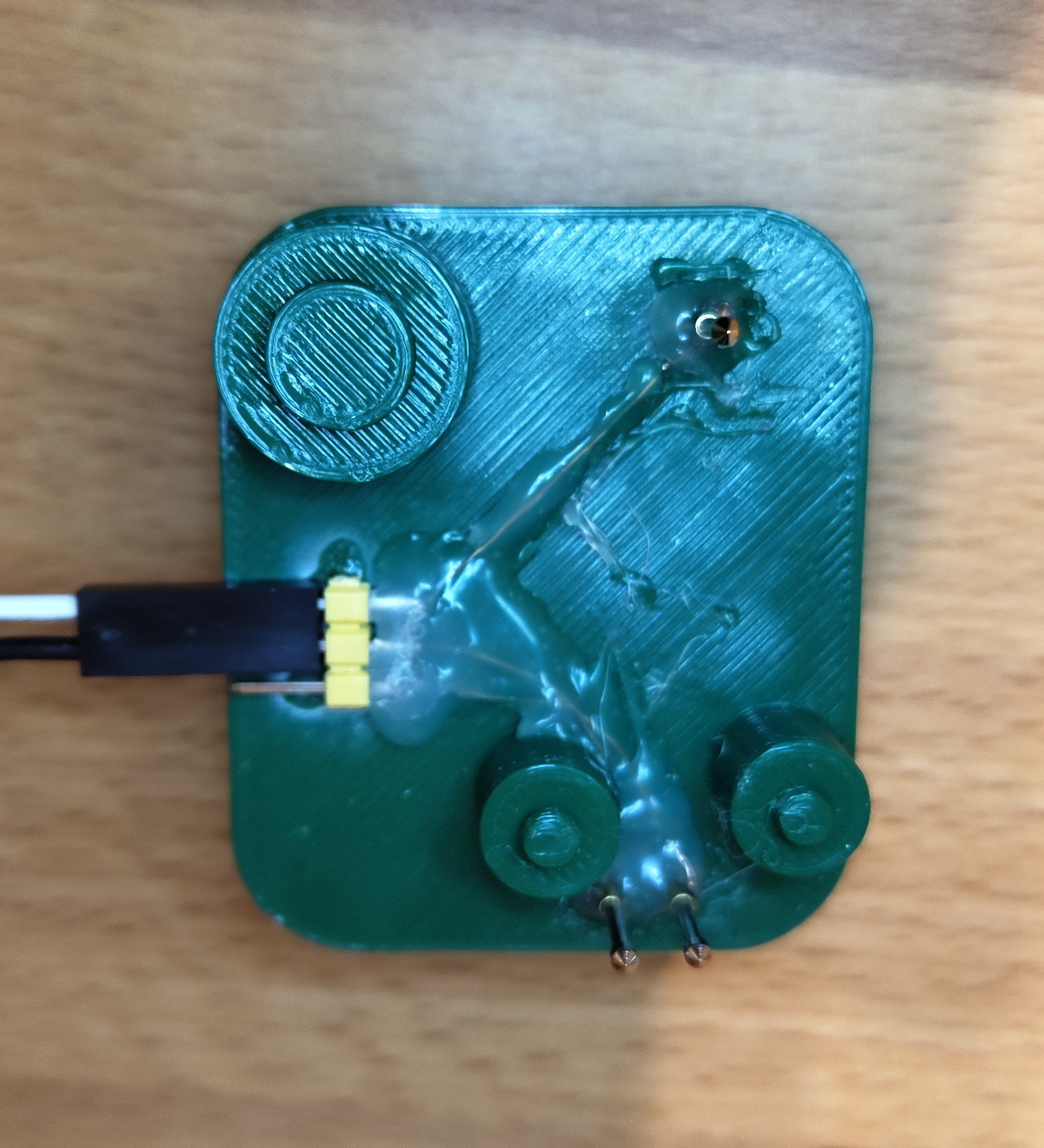
The firmware is uploaded over UDPI, the badge exposes the programming pin on the back which requires a pogopin to contact it. To make this process easier I 3D printed a very simple pogopin jig, which the badge can be placed over.
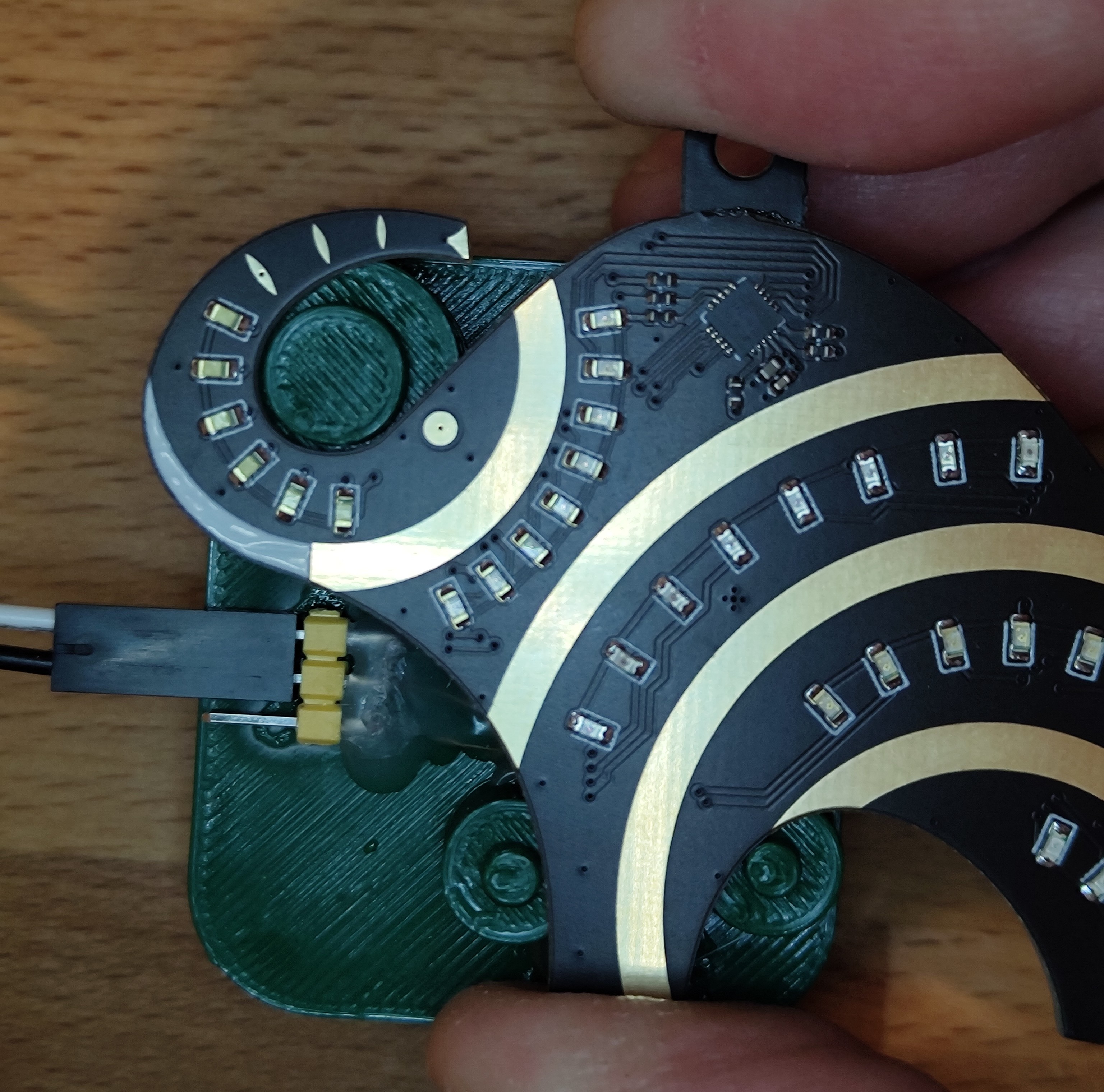
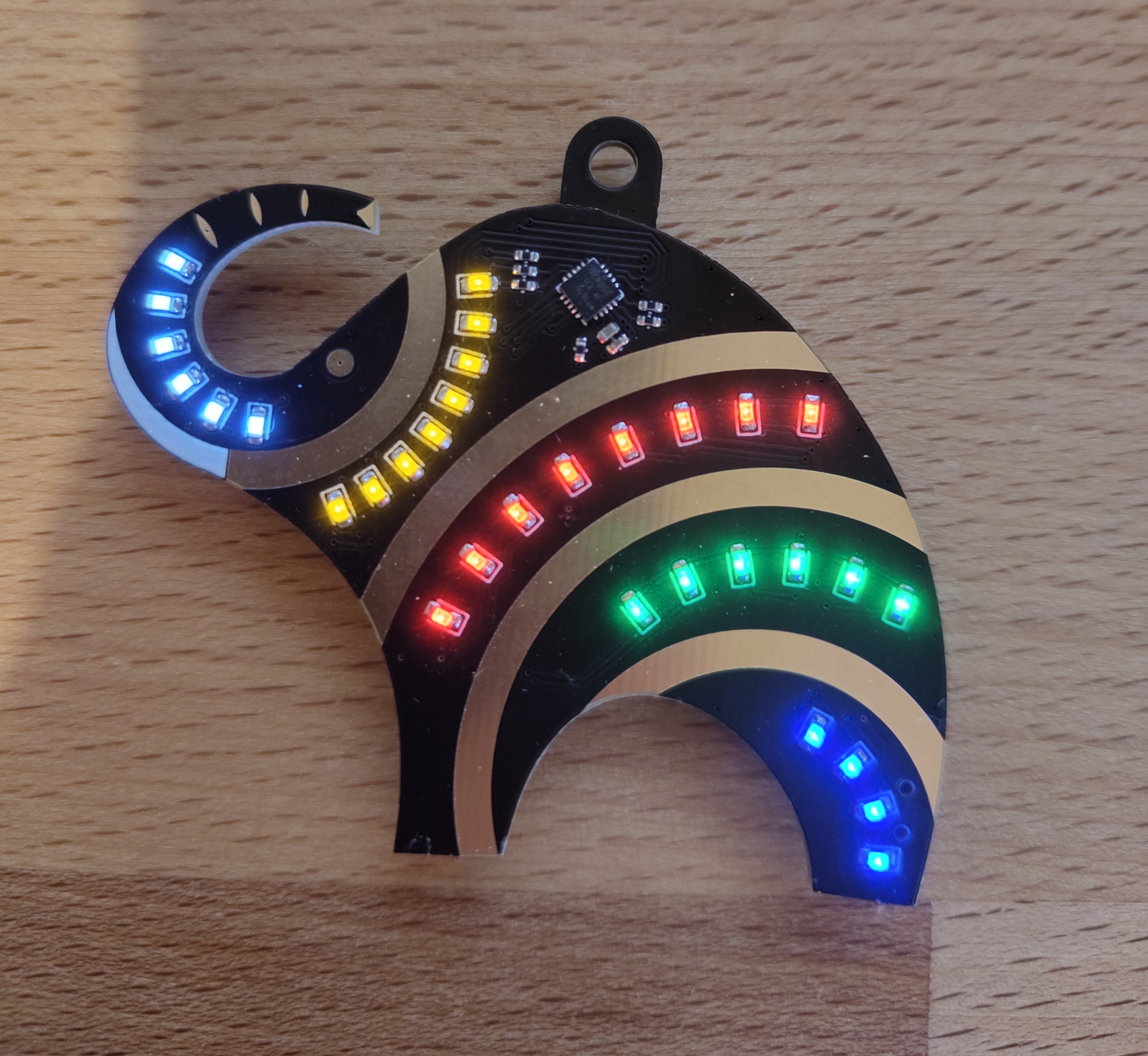
End Result
I'm pretty please with how they came out in the end.